MARCA DIURNA EN SEÑALES
El problema que se intenta tratar es el de definir una metodología para decidir cuando una señal está para pintar o no, hablando de su marca diurna.
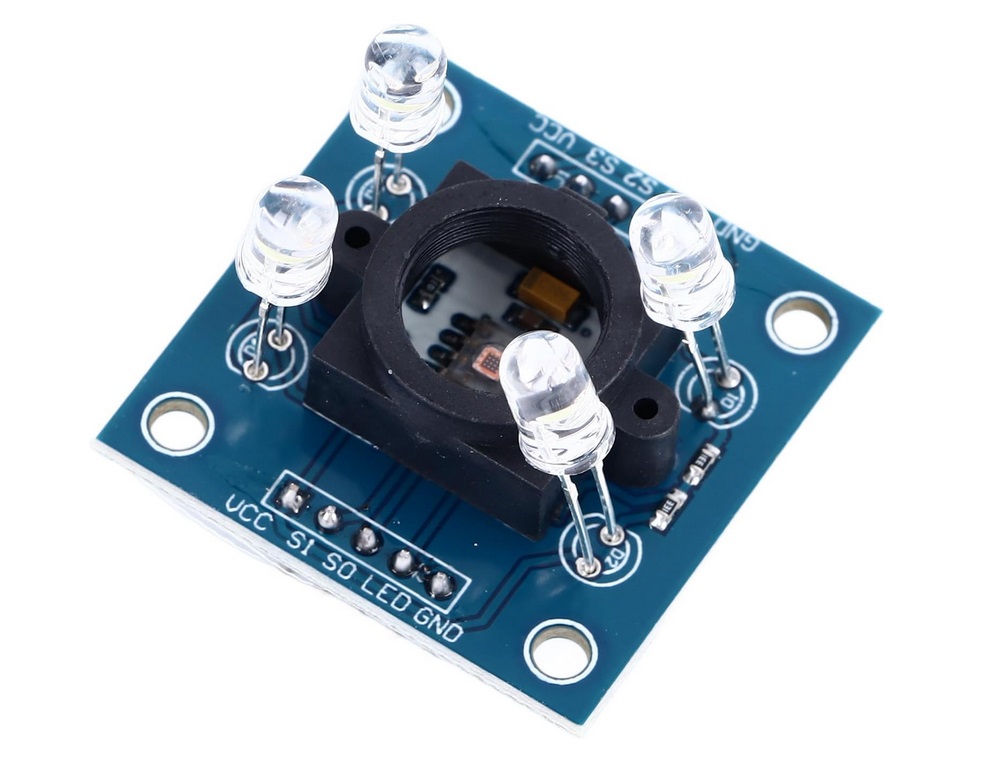
La idea es implementar un sistema que sea capaz de leer los colores y para ello se pensó en realizarlo con la ayuda de una placa arduino y un sensor de color, en particular el TCS3200 que es que mejores resultados ha ofrecido hasta el momento.
Por un lado para el desarrollo del arduino nos hemos apoyado del siguiente video.
Se ha completado información con las recomendaciones de la IALA E200-1 y E200-3, ya que técnicamente el proceso es el siguiente:
Con la ayuda del sensor conectado a un arduino, lo que se obtiene son tres valores R, G y B de cuanto rojo, cuanto verde y cuanto azul hay respectivamente. Sin embargo para llevarlo a la gráfica que nos encontramos en el GEPAN hay que traducir dichos valores a valores X Y Z según CIE 1931. Y no solo eso, sino además llevarlo a una forma normalizada.
Se han consultado los siguientes enlaces para ampliar información más detallada sobre el proceso de conversión de RGB a XYZ:
La conclusión y haciendolo todo breve, finalmente es una multiplicación algebraica de matrices. La matriz RGB 3×1 se premultiplica por una matriz 3×3 para obtener una matriz XYZ de 3×1.
Una vez obtenidos los valores XYZ, se normalizan de la siguiente manera:
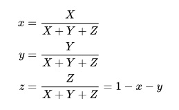
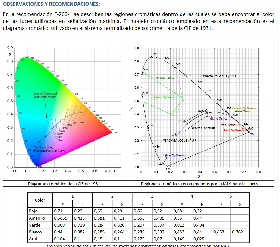
Y ya con los valores de x e y se puede entrar en la siguiente gráfica para ver si el punto obtenido cae en la zona válida o no.
Adjunto el codigo empleado en arduino.
/*
  Color Sensor Calibration
  color-sensor-calib.ino
  Calibrate RGB Color Sensor output Pulse Widths
  Uses values obtained for RGB Sensor Demo sketch

  DroneBot Workshop 2020
  https://dronebotworkshop.com
*/

//RGB values to XYZ using the Wide RGB D65 conversion formula
/* float a11 = 0.664511;float a12 = 0.154324;float a13 = 0.162028;
float a21 = 0.283881;float a22 = 0.668433;float a23 = 0.047685;
float a31 = 0.000088;float a32 = 0.072310;float a33 = 0.986039;  */

//RGB values to XYZ using the  adobe D65 conversion formula
//* 0.5767309  0.1855540  0.1881852
// 0.2973769  0.6273491  0.0752741
// 0.0270343  0.0706872  0.9911085 */

//RGB values to XYZ using the  sRGB D65 conversion formula
/* float a11 = 0.4124564;float a12 = 0.3575761;float a13 = 0.1804375;
float a21 = 0.2126729;float a22 = 0.7151522;float a23 = 0.0721750;
float a31 = 0.0193339;float a32 = 0.1191920;float a33 = 0.9503041; */

//TO COPY HERE THE ONES TO USE
float a11 = 0.649926;
float a12 = 0.103455;
float a13 = 0.197109;
float a21 = 0.234327;
float a22 = 0.743075;
float a23 = 0.022598;
float a31 = 0.0000000;
float a32 = 0.053077;
float a33 = 1.035763;


float R, G, B, C;


// Define color sensor pins

#define S0 4
#define S1 5
#define S2 6
#define S3 7
#define sensorOut 8

#include <TCS3200.h>
TCS3200 tcs3200(S0, S1, S2, S3, sensorOut);
// Define color labels for identification
String color_indices[] = { "Red", "Green", "Blue" };
// Define RGB color values corresponding to the color labels
RGBColor color_values[] = {
  { 255, 0, 0 },  // Red
  { 0, 255, 0 },  // Green
  { 0, 0, 255 },  // Blue
};


int redMin = 22;
int redMax = 310;
int greenMin = 17;
int greenMax = 333;
int blueMin = 18;
int blueMax = 263;

int redValue;
int greenValue;
int blueValue;
int clearValue;

// Variables for Color Pulse Width Measurements

int redPW = 0;
int greenPW = 0;
int bluePW = 0;
int clearPW = 0;

void setup() {

  // Set S0 - S3 as outputs
  pinMode(S0, OUTPUT);
  pinMode(S1, OUTPUT);
  pinMode(S2, OUTPUT);
  pinMode(S3, OUTPUT);

  // Set Sensor output as input
  pinMode(sensorOut, INPUT);

  // Set Pulse Width scaling to 20%
  digitalWrite(S0, HIGH);
  digitalWrite(S1, LOW);

  // Setup Serial Monitor
  Serial.begin(9600);
}

void loop() {
  String color = "";
  // Read Red Pulse Width
  redPW = getRedPW();
  redValue = map(redPW, redMin, redMax, 255, 0);
  R = constrain(redValue, 0, 255);
  //R=redPW;

  // Delay to stabilize sensor
  delay(200);

  // Read Green Pulse Width
  greenPW = getGreenPW();
  greenValue = map(greenPW, greenMin, greenMax, 255, 0);
  G = constrain(greenValue, 0, 255);
  //G=greenPW;

  // Delay to stabilize sensor
  delay(200);

  // Read Blue Pulse Width
  bluePW = getBluePW();
  blueValue = map(bluePW, blueMin, blueMax, 255, 0);
  B = constrain(blueValue, 0, 255);
  //B=bluePW;

  //clear
  clearPW = getClearPW();
  //clearValue = map(clearPW, blueMin, blueMax, 255, 0);
   //C = constrain(clearValue, 0, 255);

  // Delay to stabilize sensor
  delay(200);

  //TRANSFORMACION A CIE
  if ((R > 210) & (G > 210) & (B > 210)) {
    color = "White";
  }
  if ((R < 40) & (G < 40) & (B < 40)) {
    color = "Black";
  }
  if ((180 <= R) & (R <= 255) & (170 <= G) & (G <= 255) & (0 <= B) & (B <= 160)) {
    color = "Yellow";
  }
  if ((G - B > 20) & (G - R > 30)) {
    color = "Green";
  }
  if ((B - G > 20) & (B - R > 40)) {
    color = "Blue";
  }
  if ((R - G > 40) & (R - B > 40)) {
    color = "Red";
  }


  Serial.print("R= ");
  Serial.print(R);
  Serial.print("  G= ");
  Serial.print(G);
  Serial.print("  B= ");
  Serial.print(B);
  Serial.print("  C= ");
  Serial.print(clearPW);
  Serial.print("    => ");


  R = getGammaCorrectedValue(R / 255);
  G = getGammaCorrectedValue(G / 255);
  B = getGammaCorrectedValue(B / 255);

  float X = (R * a11 + G * a12 + B * a13);
  float Y = (R * a21 + G * a22 + B * a23);
  float Z = (R * a31 + G * a32 + B * a33);
  //Calculate the xy values from the XYZ values
  float x = (X / (X + Y + Z));
  float y = (Y / (X + Y + Z));


  if ((x >= 0.60) & (x <= 0.75) & (y >= 0.29) & (y <= 0.34)) color = "ROJO RAL VALIDO";
  if ((x >= 0.55) & (x <= 0.61) & (y >= 0.39) & (y <= 0.45)) color = "AMARILLO RAL VALIDO";
  if ((x >= 0.013) & (x <= 0.30) & (y >= 0.38) & (y <= 0.76)) color = "VERDE RAL VALIDO";
  if ((x >= 0.29) & (x <= 0.48) & (y >= 0.27) & (y <= 0.44)) color = "BLANCO RAL VALIDO";
  if (clearPW>80 & ((1-x-y)<0.05) &(x >= 0.250) & (x <= 0.35) ) color = "NEGRO RAL VALIDO";


  /*   if ((color == "Green") & (y >= 0.493 - 0.524 * x) & (y >= 0.243 + 0.670 * x))
    color += " VALIDO";

  //if ((color == "Red") & (y <= 0.910 - 0.051 * x) & (y >= 0.314 + 0.047 * x) & (y <= 0.345 - 0.051 * x))
  if ((color == "Red") & (x > 0.65) & (y > 0.29))
    color += " VALIDO"; */

  //FIN TRANSFORMACION A CIE


  // Print output to Serial Monitor

  Serial.print(color);
  Serial.print("         X: ");
  Serial.print(X);
  Serial.print(" Y: ");
  Serial.print(Y);
  Serial.print(" Z: ");
  Serial.print(Z);
  Serial.print("  -   x:");
  Serial.print(x);
  Serial.print(" y:");
  Serial.print(y);
  Serial.print(" z:");
  Serial.print(1 - x - y);
  Serial.println();
}


// Function to read Red Pulse Widths
int getRedPW() {

  // Set sensor to read Red only
  digitalWrite(S2, LOW);
  digitalWrite(S3, LOW);
  // Define integer to represent Pulse Width
  int PW;
  // Read the output Pulse Width
  PW = pulseIn(sensorOut, LOW);
  // Return the value
  return PW;
}

// Function to read Green Pulse Widths
int getGreenPW() {

  // Set sensor to read Green only
  digitalWrite(S2, HIGH);
  digitalWrite(S3, HIGH);
  // Define integer to represent Pulse Width
  int PW;
  // Read the output Pulse Width
  PW = pulseIn(sensorOut, LOW);
  // Return the value
  return PW;
}

// Function to read Blue Pulse Widths
int getBluePW() {

  // Set sensor to read Blue only
  digitalWrite(S2, LOW);
  digitalWrite(S3, HIGH);
  // Define integer to represent Pulse Width
  int PW;
  // Read the output Pulse Width
  PW = pulseIn(sensorOut, LOW);
  // Return the value
  return PW;
}

// Function to read CLEAR Pulse Widths
int getClearPW() {

  // Set sensor to read Blue only
  digitalWrite(S2, HIGH);
  digitalWrite(S3, LOW);
  // Define integer to represent Pulse Width
  int PW;
  // Read the output Pulse Width
  PW = pulseIn(sensorOut, LOW);
  // Return the value
  return PW;
}

float getGammaCorrectedValue(float value) {
  if (value > 0.04045) {
    return pow((value + 0.055) / (1.0 + 0.055), 2.4);
  } else
    return (value / 12.92);
}
Proximamente incluiré fotos, resultados así como información más detallada.